Device Sensors
You can configure different sensors based on the device model. Once configured, a sensor’s settings can be synchronized with other devices.
Supported Sensor Types
Section titled “Supported Sensor Types”| Sensor Type | Supported Devices | Sensor Number Required |
|---|---|---|
| Temperature and Humidity Sensor | 1-8 channels | No |
| Bluetooth Sensor | 2 devices | Yes |
| Alcohol Tester | 1 device | Yes |
| Tire Pressure Sensor | 4-36 tires | Yes |
| CAN Bus Sensor | 1 device | Yes |
| Liquid Level Sensor | 1 device | No |
| ADC Voltage Sensor | 1 device | No |
Basic Configuration Steps
Section titled “Basic Configuration Steps”-
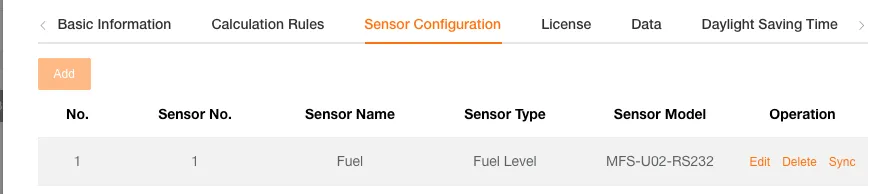
Create Sensor Configuration
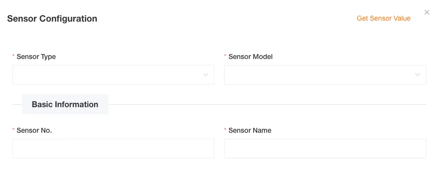
Go to Device Management → Device Edit → Peripheral Configuration page, click the “Add” button to open the configuration dialog.
-
Fill in Basic Information
- Sensor Type: Select the sensor type (temperature and humidity, Bluetooth, tire pressure, etc.)
- Sensor Model: Select the specific model based on the type
- Sensor Number: Enter a number between 1-99 (required for some sensors)
- Sensor Name: Enter the display name of the sensor
-
Configure Sensor Parameters and Save
Fill in the corresponding configuration parameters based on the selected sensor type. Click the “OK” button to save the configuration, and the system will automatically validate the data format and submit it to the server.
-
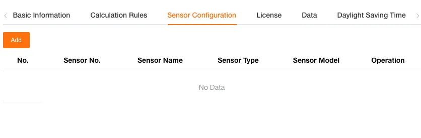
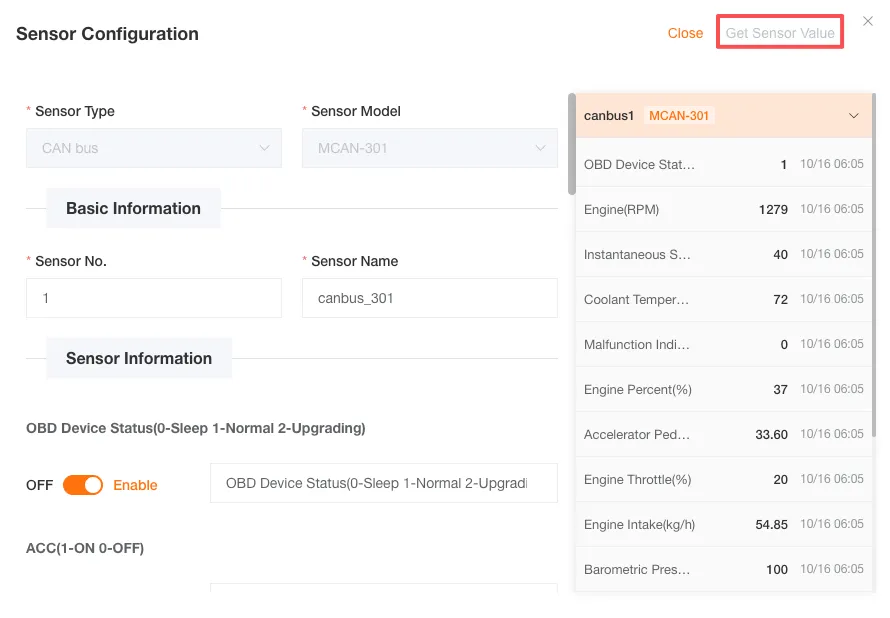
View Sensor Data
After configuration is complete, you can view the real-time uploaded data of the sensor at the bottom of the page. You can view the last reported data of the sensor within the past three days.
Detailed Sensor Configuration
Section titled “Detailed Sensor Configuration”Temperature and Humidity Sensor
Section titled “Temperature and Humidity Sensor”Features:
- Supports 1-4 temperature and humidity channels
- Each channel can be independently configured with temperature and humidity field names
- Input fields display default values only on first fill
-
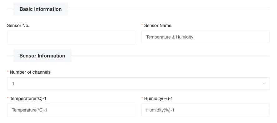
Fill in Basic Information
- Sensor Name: Enter the display name of the sensor (required)
- Sensor Number: Enter a number between 1-99 (optional)
-
Select Number of Temperature and Humidity Channels
Select the number of channels from the dropdown menu (1-4, default is 1 channel). After selection, the corresponding name configuration fields will be displayed based on the quantity.
-
Configure Each Channel
Channel 1 Configuration:
- Temperature (℃) Field Name: Enter the display name of the temperature sensor (default: Temperature (℃)-1, required)
- Humidity (%) Field Name: Enter the display name of the humidity sensor (default: Humidity (%)-1, required)
Channel 2 Configuration (if 2 or more channels are selected):
- Temperature (℃) Field Name: Enter the display name of the temperature sensor (default: Temperature (℃)-2, required)
- Humidity (%) Field Name: Enter the display name of the humidity sensor (default: Humidity (%)-2, required)
And so on, configure according to the selected number of channels.
-
Save Configuration
Configuration Example:
Assume configuring a 2-channel temperature and humidity sensor to monitor the compartment environment:
-
Channel 1:
- Temperature (℃): Front Compartment Temperature
- Humidity (%): Front Compartment Humidity
-
Channel 2:
- Temperature (℃): Rear Compartment Temperature
- Humidity (%): Rear Compartment Humidity
Bluetooth Sensor
Section titled “Bluetooth Sensor”Features:
- Supports up to 2 Bluetooth devices
- Each device can be configured as a door magnet sensor or fuel detection sensor
- Input fields display default values only on first fill
- Calibration rules are automatically generated based on configuration content
-
Fill in Basic Information
- Sensor Name: Enter the display name of the sensor (required)
- Sensor Number: Enter a number between 1-99 (required)
-
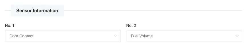
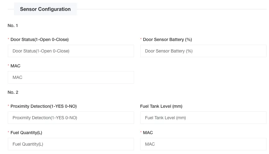
Configure Sensor Information
Select the device type for each number (1 and 2):
- Empty: No configuration content
- Door Magnet Sensor
- Fuel Detection Sensor
Number 1 Configuration:
Select “Door Magnet Sensor”:
- Door Status Field Name: Enter the display name of the door status (default: Door Status, required)
- Door Magnet Battery (%) Field Name: Enter the display name of the battery level (default: Door Magnet Battery (%), required)
- MAC Field Name: Enter the display name of the MAC address (default: MAC Address, required)
Select “Fuel Detection Sensor”:
- Personnel Proximity Field Name: Enter the display name of the proximity detection (default: Personnel Proximity Detection, required)
- Fuel Tank Level Field Name: Enter the display name of the fuel tank level (default: Fuel Tank Level, required)
- Remaining Fuel (L) Field Name: Enter the display name of the fuel amount (default: Remaining Fuel, required)
- MAC Field Name: Enter the display name of the MAC address (default: MAC Address, required)
Number 2 Configuration:
Configuration is the same as Number 1, can select “Empty”, “Door Magnet Sensor” or “Fuel Detection Sensor”
-
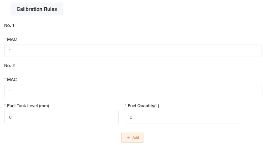
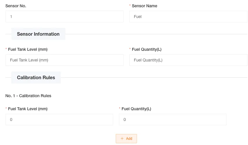
Configure Calibration Rules
Calibration rules are automatically generated based on the configuration content above:
- Configuration content is empty: No calibration
- Configuration content is door magnet sensor: MAC address calibration only
- Configuration content is fuel detection sensor: MAC address + level calibration
Fuel Detection Sensor Calibration Configuration:
- MAC Address: Input field (default value is *, indicating no restriction, required)
- Calibration Points: Add multiple calibration points
- Fuel Tank Level: Enter the level value (mm)
- Remaining Fuel (L): Enter the corresponding fuel value (L)
- Supports dynamically adding/deleting calibration points
- First point defaults to 0 0 when adding
Tire Pressure Sensor
Section titled “Tire Pressure Sensor”Features:
- Supports 4-36 tires
- Each tire can be independently configured with RFID, tire pressure, and tire temperature fields
- Automatically generates tire data
-
Fill in Basic Information
- Sensor Name: Enter the name of the sensor (required)
- Sensor Number: Enter the number of the sensor (required)
-
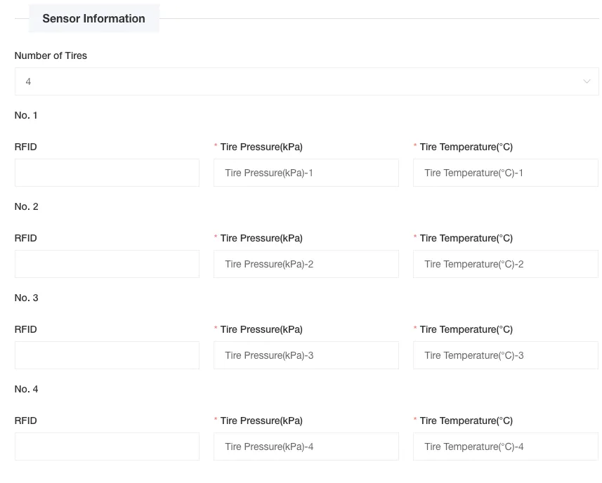
Configure Sensor Information
- Number of Tires: Select the number of tires from the dropdown menu (4-36, default is 4, required)
Based on the selected number of tires, the system will display the corresponding number of configuration fields. Each tire needs to be configured as follows:
Tire 1 Configuration:
- RFID: Enter the RFID identifier of the tire (optional)
- Tire Pressure (kPa): Enter the display name of the tire pressure field (default value is “Tire Pressure (kPa)-1”, required)
- Tire Temperature (℃): Enter the display name of the tire temperature field (default value is “Tire Temperature (℃)-1”, required)
Tire 2 Configuration:
- RFID: Enter the RFID identifier of the tire (optional)
- Tire Pressure (kPa): Enter the display name of the tire pressure field (default value is “Tire Pressure (kPa)-2”, required)
- Tire Temperature (℃): Enter the display name of the tire temperature field (default value is “Tire Temperature (℃)-2”, required)
And so on, configure according to the selected number of tires.
-
Save Configuration
Configuration Example:
Tire 1 Configuration:
- RFID: 1b02438a
- Tire Pressure (kPa): Front Left Tire Pressure
- Tire Temperature (℃): Front Left Tire Temperature
Tire 2 Configuration:
- RFID: 1b02438a
- Tire Pressure (kPa): Tire Pressure (kPa)-2
- Tire Temperature (℃): Tire Temperature (℃)-2
Tire 3 Configuration:
- RFID: (leave blank)
- Tire Pressure (kPa): Tire Pressure (kPa)-3
- Tire Temperature (℃): Tire Temperature (℃)-3
Alcohol Tester
Section titled “Alcohol Tester”Features:
- Single device configuration
- Supports alcohol concentration detection
- Automatically generates device identification information
-
Fill in Basic Information
- Sensor Name: Enter the name of the sensor (required)
- Sensor Number: Enter the number of the sensor (required)
-
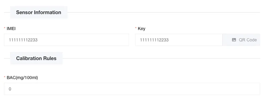
Configure Sensor Information
- IMEI: Enter the device IMEI number (default value is device number, required)
- Key: Enter the device key (default value is device number, required)
- QRCode: QR code information (automatically generated by system)
-
Save Configuration
CAN Bus Sensor
Section titled “CAN Bus Sensor”Features:
- Reads vehicle CAN bus data
- Supports 18 types of data items
- All data items are selected by default
-
Fill in Basic Information
- Sensor Name: Enter the name of the sensor (required)
- Sensor Number: Enter the number of the sensor (required)
-
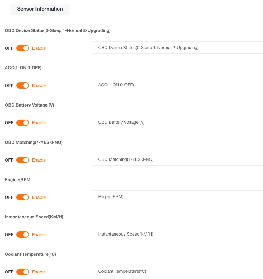
Configure Sensor Information
Select the data items to be collected. All data items are selected by default:
- OBD Device Status: OBD Device Status (default selected, required)
- OBD Battery Voltage (V): OBD Battery Voltage (V) (default selected, required)
- OBD Adapter: OBD Adapter (default selected, required)
- Engine Speed (RPM): Engine Speed (RPM) (default selected, required)
- Instantaneous Speed (KM/H): Instantaneous Speed (KM/H) (default selected, required)
- Coolant Temperature (℃): Coolant Temperature (℃) (default selected, required)
- Fault Light: Fault Light (default selected, required)
- Engine Load Percentage: Engine Load Percentage (default selected, required)
- Throttle Pedal Position: Throttle Pedal Position (default selected, required)
- Engine Throttle: Engine Throttle (default selected, required)
- Engine Intake Air Mass Flow Rate: Engine Intake Air Mass Flow Rate (default selected, required)
- Air Pressure (kPa): Air Pressure (kPa) (default selected, required)
- Time After Engine Start: Time After Engine Start (default selected, required)
- VIN: VIN (default selected, required)
- Total Mileage (KM): Total Mileage (KM) (default selected, required)
- Total Fuel Consumption (L): Total Fuel Consumption (L) (default selected, required)
- Fuel Level (%): Fuel Level (%) (default selected, required)
-
Save Configuration
Liquid Level Sensor
Section titled “Liquid Level Sensor”Features:
- Supports liquid level detection
- Can configure level-to-capacity conversion
- Supports dynamically adding calibration points
-
Fill in Basic Information
- Sensor Name: Enter the name of the sensor (required)
-
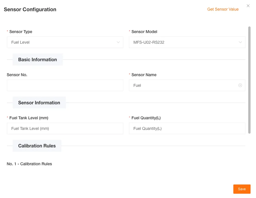
Configure Sensor Information
- Fuel Tank Level (mm): Enter the display name of the level field (default value is the corresponding internationalization text of the system, required)
- Remaining Fuel (L): Enter the display name of the fuel field (default value is the corresponding internationalization text of the system, required)
-
Configure Calibration Rules
Add multiple calibration points to achieve level-to-fuel conversion:
- Fuel Tank Level (mm): Enter the level value (mm)
- Remaining Fuel (L): Enter the corresponding fuel value (L)
The first point defaults to 0 0 when adding, and supports dynamically adding/deleting calibration points.
-
Save Configuration
ADC Voltage Sensor
Section titled “ADC Voltage Sensor”Features:
- Supports ADC voltage collection
- Can configure voltage-to-fuel conversion
- Supports dynamically adding calibration points
-
Fill in Basic Information
- Sensor Name: Enter the name of the sensor (required)
-
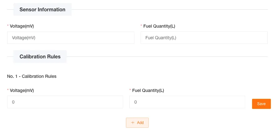
Configure Sensor Information
- Voltage (mV): Enter the display name of the voltage field (default value is the corresponding internationalization text of the system, required)
- Remaining Fuel (L): Enter the display name of the fuel field (default value is the corresponding internationalization text of the system, required)
-
Configure Calibration Rules
Add multiple calibration points to achieve voltage-to-fuel conversion:
- Voltage (mV): Enter the voltage value (mV)
- Remaining Fuel (L): Enter the corresponding fuel value (L)
The first point defaults to 0 0 when adding, and supports dynamically adding/deleting calibration points.
-
Save Configuration