AI Features
AI Overview
Section titled “AI Overview”Types of Algorithms
Section titled “Types of Algorithms”Function Abbreviation | Full Name | Description |
|---|---|---|
| DMS | Driving State Monitoring System | Uses images captured by the DMS camera to monitor the driver’s driving behavior and physiological state through visual tracking, object detection, and motion recognition technologies, thereby alerting and warning the driver. |
| ADAS | Advanced Driver Assistance System | Monitors the driving environment ahead of the vehicle in real time. When the system detects a potential hazard, it issues an alert to warn the driver of abnormal vehicle or road conditions. |
| DMSX | Driver Seat Belt Monitoring | Using images captured by a top-view camera, the system extracts the image area corresponding to the driver’s torso and employs visual tracking, object detection, and motion recognition technologies to monitor the driver’s behavior, thereby providing reminders and warnings. |
| BSD | Blind Spot Detection | Cameras installed around the front, rear, and both sides of the vehicle continuously detect objects (such as pedestrians) within the blind spots on either side of the vehicle, eliminating visual blind spots. If an object enters the blind spot, an alert is issued to warn the driver of pedestrians in the blind spot area. |
Algorithm Camera Specification Requirements
Section titled “Algorithm Camera Specification Requirements”| Algorithm Type | DMS | ADAS | BSD | DMSX | 360 |
|---|---|---|---|---|---|
| Camera | DMS Camera | Standard Camera | Standard Camera Fisheye Camera | Standard Camera | Fisheye Camera |
| Alert Types | Drowsy Driving | Phone Use | Smoking Distracted Driving | Driver Abnormalities Device Obstruction | Infrared Blockage Auto Calibration |
| Category | Configuration Guidelines |
|---|---|
| BSD Camera Selection | 1. Left and right blind spots only: Standard or fisheye cameras; 2. Includes front and rear blind spots: Cameras must be fisheye; 3. 3-channel blind spots: All cameras must be fisheye |
| Channel Quantity Constraints | 1. Different AI algorithms cannot share the same channel; duplicate configurations cannot be saved; 2. Total number of AI channels + passenger flow channels ≤ 4; 3. AI channels and passenger flow channels cannot be reused |
| ADAS Alarm Logic | Pedestrian collision: Alarm triggered when vehicle speed is between [Set Speed - Threshold Speed] Lane Deviation: (-20 to 20 cm); +20 cm represents the distance between the vehicle’s wheel hub and the lane line |
| BSD Alarm Logic | Alarm triggered only when vehicle speed < set speed limit; no tiered parameters |
| DMS Sensitivity | Unit: seconds; alarm triggered only after anomaly persists for the set duration to prevent false alarms |
| ADAS/BSD Sensitivity Level | Selectable from levels 1–10; lower numbers indicate higher sensitivity |
| Specific Model | List of Supported Algorithms | Maximum Number of Concurrent Algorithms |
|---|---|---|
| MC201S | None | 0 |
| MC202E | None | 0 |
| MC202P | ADAS、DMS | 2 |
| MC202X | ADAS、DMS | 2 |
| MC401P | ADAS、DMS | 2 |
| MC401X | ADAS、DMS、BSD | 2 |
| MC402 | ADAS、DMS、BSD、DMSX | 4 |
| MC403 | ADAS、DMS、BSD | 2 |
| MC904 | ADAS、DMS、BSD、DMSX | 4 |
| MC908 | ADAS、DMS、BSD、DMSX、360 | 5 |
| MC908F | ADAS、DMS、BSD 、DMSX | 4 |
| MC908W | ADAS、DMS、BSD、DMSX | 4 |
| MC912 | ADAS、DMS、BSD、DMSX、360 | 5 |
AI Certification
Section titled “AI Certification”Device Category | Activation Scenario | Prerequisite Steps | Primary Method for Obtaining Authentication Files |
|---|---|---|---|
| New Device | Has never had any AI algorithms activated | 1. Update the device extension 2. Provide the device chip ID 3. Ensure the device is properly connected to the internet | After we complete the algorithm activation, simply restart the device to quickly obtain the authentication file |
| Existing Device | Has had at least one algorithm enabled; needs to add a new AI algorithm | 1. Provide the device chip ID 2. Ensure the device is properly connected to the internet | After we complete the algorithm activation, re-obtain the AI authentication file using any of the following methods—restarting the device can speed up the process Remote control buttons: Open the device info page, then press the buttons in sequence: “5” → “1” → “7” |
AI Calibration
Section titled “AI Calibration”Calibration steps required before triggering AI alerts:
-
DMS Calibration
Section titled “DMS Calibration”-
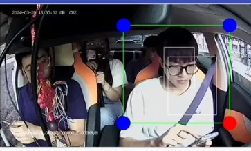
MC201, MC202, MC401, and MC403 Series Products
A DMS calibration frame is displayed. You can move, zoom in, or zoom out the calibration frame by selecting the focal point or dragging the screen. Position the frame so that the driver’s eyes are directly facing the camera. Once a white recognition frame appears within the DMS calibration frame indicating successful face detection, the DMS calibration is complete.
-
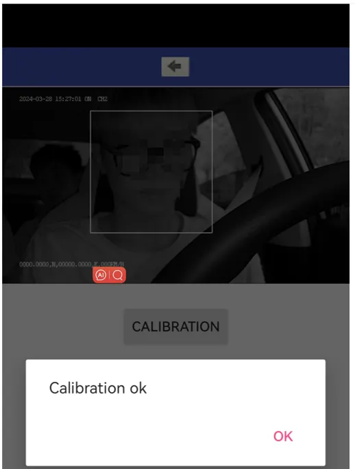
MC402, MC904, MC908, MC912 Series Products
No DMS calibration frame is displayed; typically, the DMS camera is mounted externally. When the driver’s eyes are directly facing the DMS camera and the device detects a white face recognition frame, DMS calibration can be performed.
-
-
ADAS Calibration
Section titled “ADAS Calibration”-
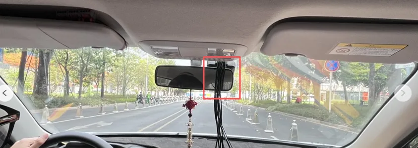
Installation Location: Mount the camera at the center of the windshield, aligned with the vehicle’s centerline. The optimal installation position is at the intersection of the horizontal line above the windshield wipers and the centerline. (Note: Ensure it is not obstructed by the windshield wipers)
-
Parameter Description:
-
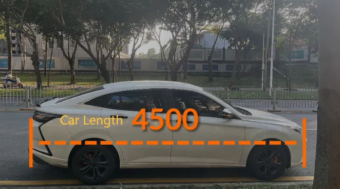
Vehicle Length (mm>0): Overall vehicle length
-
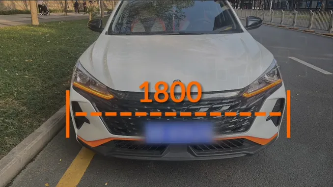
Vehicle Width (mm>0): Distance between the outer edges of the two tires
-
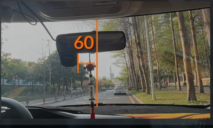
Distance between the camera and the vehicle center (mm, -1000 to 1000): When seated in the driver’s seat, if there is a distance difference between the device mounting point and the vehicle center point, that difference is the distance between the camera and the vehicle center. Positive distance indicates the device is on the left; negative distance indicates the device is on the right (left positive, right negative)
-
Distance from camera to front bumper (mm, 0–4000,
This parameter is only supported for the MC402, MC904, MC908, and MC912 series):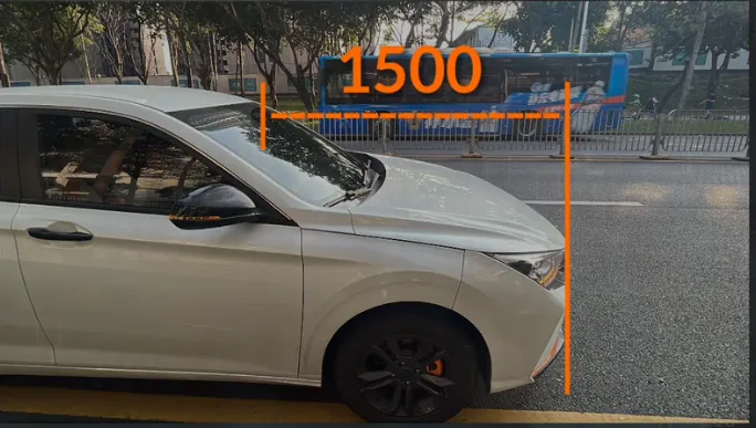
-
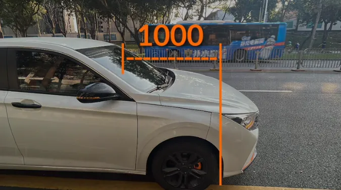
Distance from the lens to the front tire (mm, 0–2000):
-
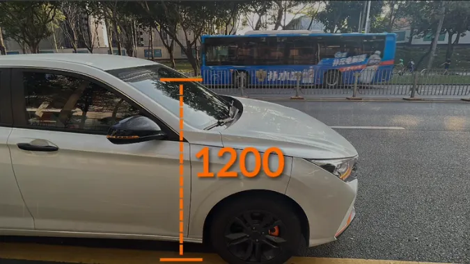
Camera height above the ground (mm, 1000–4000):
-
Camera focal length (mm) ( The smaller the value, the wider the field of view; the larger the value, the larger distant objects will appear.
This parameter is only supported for the MC402, MC904, MC908, and MC912 series products -
Sensor Size (Pixel Pitch in mm/pixel) (Recommendation: Do not modify ): The sensor size describes the physical dimensions of the camera’s image sensor. The pixel pitch refers to the distance between adjacent pixels on the image sensor. It can be calculated by dividing the sensor’s dimensions (width and height) by the number of pixels.
This parameter is only supported for the MC402, MC904, MC908, and MC912 series products -
Pitch Angle: (degrees, 20–80) (Recommendation: Do not modify ): Refers to the angle between the X-axis of the camera coordinate system and the horizontal plane. Simply put, this is the angle between the camera axis (along the camera’s direction) and the ground plane (horizontal plane); it is positive when the camera is looking up and negative when it is looking down.
This parameter is only supported by the MC201, MC202, MC401, and MC403 series products -
Yaw Angle (degrees, 40–120) (Recommendation: Do not modify ): The angle between the projection of the xB axis in the camera coordinate system onto the horizontal plane and the xg axis in the ground coordinate system (on the horizontal plane, pointing toward the target is positive).
This parameter is supported only by the MC201, MC202, MC401, and MC403 series products -
The following parameters are time-based thresholds used by the algorithm to detect when an event is about to occur. At a constant speed, the larger the time parameter, the greater the distance at which the event is triggered. (Recommendation: Do not modify )
- Too Close to Vehicle Ahead (ms, 500–6000), Pedestrian Collision (ms, 500–6000), Front Vehicle Collision (ms, 500–6000)
-
Lane Departure (cm, -200 to 100) (Recommendation: Do not modify ): This parameter represents the distance the device’s algorithm detects the camera has shifted. Negative values indicate crossing the lane line, while positive values indicate being close to the lane line
-
-
Calibration
-
MC201, MC202, MC401, and MC403 Series Products
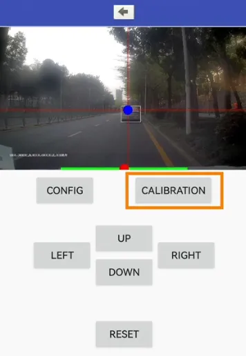
- Recommendation: After installing the camera, find a flat surface with a vehicle directly in front of the camera and position the camera to face the vehicle head-on (approximately 50 meters away). Customers should select the camera height based on their specific needs; it should not be too low, as this would result in a short distance between the engine height line and the horizon line, leading to a shorter algorithm recognition range
- Open the ADAS calibration interface in the configuration app (MXTool, MCTool). Move the green line on the screen to the hood, and move the red line to the center of the horizon and vertical lines (Horizontal: the horizon line at the farthest point of the field of view; Vertical: the centerline between the left and right lane lines) to complete calibration.
-
MC402, MC904, MC908, MC912 Series Products
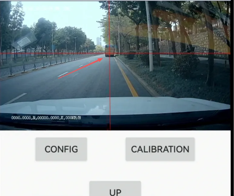
- Compared to the products above, these models lack the engine height line; otherwise, the calibration steps are the same as for Product A
-
-
-
BSD Calibration
Section titled “BSD Calibration”-
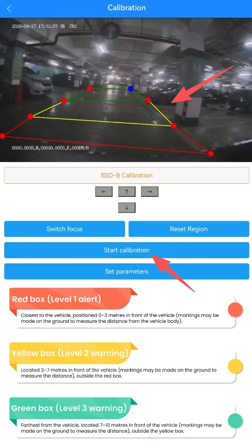
Environment Preparation Use a flat, open, and unobstructed hard surface (such as a standard parking lot) so that the calibration frames can be placed flat on the ground.
-
Calibration Standards
- Calibration Frames: Place the red, yellow, and green frames flat on the ground; their combined area should match the vehicle’s blind spot.
- Warning Zone Distances:
- Red box (Level 1): 0–3 meters to the rear and side of the vehicle
- Yellow box (Level 2): 3–7 meters to the rear and side of the vehicle, located outside the red box
- Green box (Level 3): 7–10 meters to the rear and side of the vehicle, located outside the yellow box
-
-
360 Calibration
Section titled “360 Calibration”-
Installation Location:
-
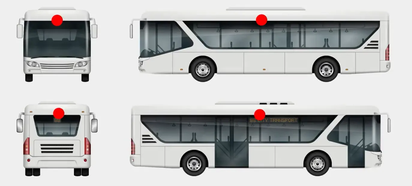
Option 1 (Optimal): Center of the vehicle roof, approximately 30–45 degrees downward. Suitable for vehicles with relatively regular external structures, such as buses and coaches.
Supports vehicles up to 12 meters in length
-
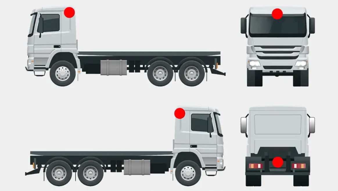
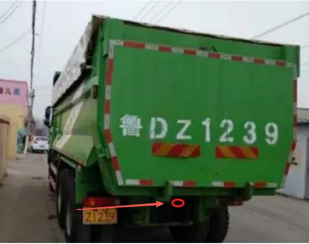
Option 2: Suitable for vehicles such as dump trucks and concrete mixers that cannot accommodate the center roof mounting position.
Supports vehicle lengths up to 9 meters
- Front camera: Installed on the front sun visor for high-roof vehicles, or on the front roof slope for flat-roof vehicles
- Left and right cameras: Installed below the side mirrors
- Rear camera: Installed on the chassis.
-
-
Installation Steps:
1. Buses and Public Transportation Vehicles
- Right Camera Installation:
- Mark a suitable position at the center of the vehicle’s roof on either side. If the center is unsuitable, install within 50 cm to the left or right of the center;
- Use self-tapping screws to mount the camera horizontally at the marked position, ensuring no significant horizontal deviation;
- If the roof curvature is too steep, add a camera-specific shim to ensure the camera’s back remains as vertical as possible relative to the ground.
- Front and Rear Camera Installation:
- Mark suitable installation positions at the center of the vehicle’s front and rear roof. If the center is unsuitable, install within a 20 cm range to the left or right of the center;
- Secure the camera horizontally at the marked location, ensuring there is no significant horizontal deviation;
- If the roof curvature is too steep, add a camera-specific shim to ensure the back of the camera is as vertical to the ground as possible.
2. Construction Vehicles
- Left and Right Camera Installation:
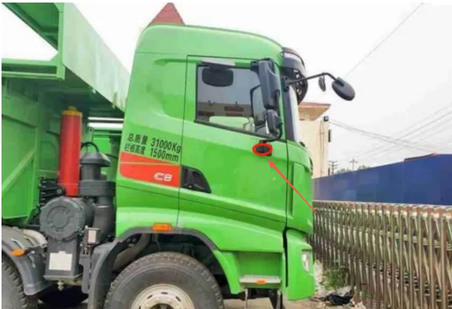
- Mark the appropriate installation positions below the left and right side mirrors. If the vehicle body is significantly wider than the front end, which may affect the camera’s field of view, install the cameras on the outward-projecting sections below the side mirrors, as shown in the figure below;
- Mount the surround-view camera horizontally at the marked location, ensuring it is as level as possible. However, if the vehicle is too long, you may slightly adjust the camera’s angle to face slightly toward the rear;
- If the curvature is too steep, add a camera-specific shim to ensure the back of the camera remains as vertical as possible relative to the ground.
- Mark the appropriate installation positions below the left and right side mirrors. If the vehicle body is significantly wider than the front end, which may affect the camera’s field of view, install the cameras on the outward-projecting sections below the side mirrors, as shown in the figure below;
- Front and Rear Camera Installation:
- Mark a suitable installation position at the center top of the vehicle’s front. If the center is unsuitable, install within a 20 cm range to the left or right of the center;
- Securely mount the surround-view camera horizontally at the marked location, ensuring there is no significant horizontal deviation;
- If the roof curvature is too steep, add a camera-specific shim to ensure the back of the camera remains as vertical as possible relative to the ground.
- Mark the center of the lower rear bumper. Install the rear camera horizontally at this location, ensuring there is no significant horizontal deviation and that the camera’s field of view is not obstructed.
3. Expected Camera Performance
Connect an external monitor to view the footage from each camera
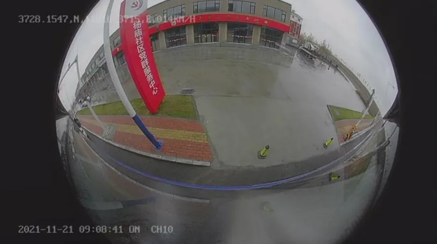
- Right Camera Installation:
-
Calibration Procedure
1. A total of four calibration cloths are required: two placed at the front and rear of the vehicle, and two on either side. The calibration cloths must not be highly reflective. Their dimensions are as follows:
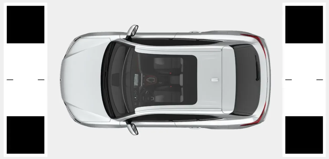
Fabric Scale Vehicle Width Range Reference Fabric Dimensions (Width) Reference Vehicle Models 1x 1.8 m–2.0 m 4.4 m Compact Cars 1.1x 2.0 m–2.2 m 4.84 m Minivans, SUVs 1.2 times 2.2 m–2.4 m 5.28 m Refrigerated trucks, medium-duty trucks 1.25 times 2.5 m 5.5 m Heavy-duty trucks, buses 3 times 6 m 13.2 m Extra-large mining trucks 2. Placement of Calibration Cloths
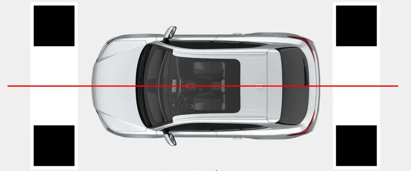
- Place the large front and rear calibration cloths parallel to the front and rear of the vehicle (no directional restriction on the left or right), aligning the center of the calibration cloths with the vehicle’s centerline. Position them so that the vertical distance between the vehicle body and the farthest checkerboard pattern is 1 m (this 1 m is not fixed; it can be adjusted by ±0.3 m based on actual conditions), as shown in the figure below, where points A and B are vertically aligned with the front of the vehicle, and points C and D are vertically aligned with the rear of the vehicle;
- Place the left and right small calibration cloths vertically parallel to the vehicle body, with the top edge of the grid 3m from the front of the vehicle (this 3m distance is not fixed; it can be adjusted forward or backward based on the camera installation position to bring the cloth closer to the left and right cameras). The edge of the grid on the side of the calibration cloth closest to the vehicle body should align with the edges of the four corner grids, as shown in the figure below, aligned with the two vertical red lines
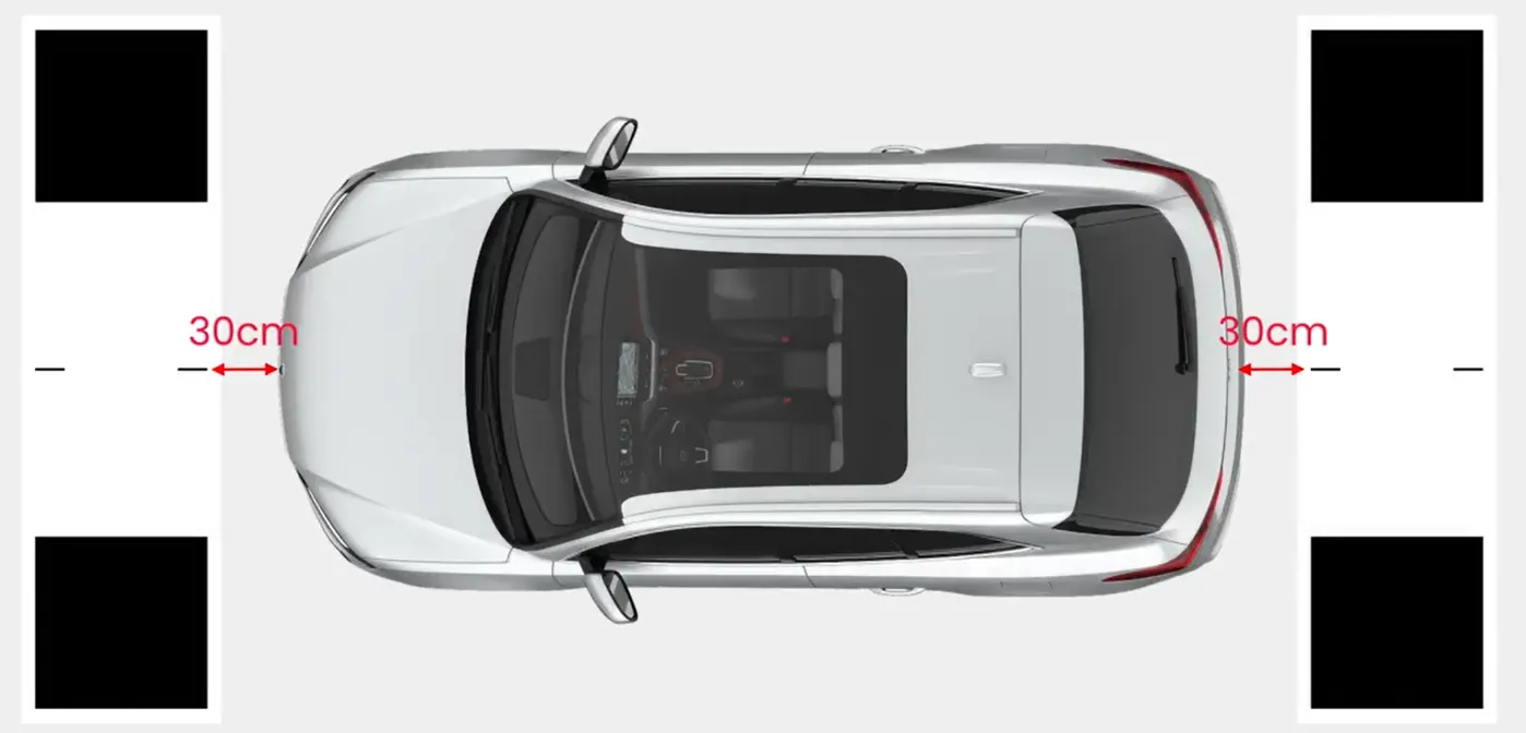
-
Measure relevant parameters
- Measure the vehicle length and width.
- Measure the vertical distance from the front and rear of the vehicle to the corner of the largest checkerboard pattern closest to the vehicle;
- Measure the horizontal distance from the left and right sides of the vehicle to the nearest corner of the largest checkerboard grid;
- Count the number of rows and columns in the four-sided checkerboard grid (view the calibration cloth placed horizontally from a vertical perspective to count the rows and columns)
-
Perform Calibration
-
Connect the mobile app to the device, open the app’s 360-degree calibration page, and check each image individually to ensure the corners of the large checkerboard are clearly visible, with no reflections.
-
Click “Set Parameters,” enter the corresponding vehicle and calibration cloth parameters. The field of view should cover the entire stitched area; the default is 20m. The fusion angle corresponds to the seam angle; the default is 45°.
Note: The distances from the front, rear, and both sides of the vehicle to the checkerboard refer to the distance to the largest checkerboard.
Parameter Name Parameter Value Parameter Name Parameter Value Vehicle Length (mm) 12000 Field of View (mm) 20000 Vehicle Width (distance between the outer edges of the two tires) (mm) 2500 Fusion Angle 45 Longitudinal Distance from Front of Vehicle to Grid (mm) 850 Horizontal Width of Corner Grids (mm) 800 Longitudinal distance from rear of vehicle to grid (mm) 850 Longitudinal height of corner grids (mm) 800 Lateral distance from left side of vehicle to grid (mm) 950 Height of center grids on all four sides (mm) 300 Horizontal distance from right side of vehicle to grid (mm) 950 Number of rows in center grid 5 Number of columns in center grid 6 -
Click to start calibration; the device will perform self-calibration and display a calibration success prompt.
-
View the “Full” section on the app page, or view the 360-degree stitching effect on the AHD screen.
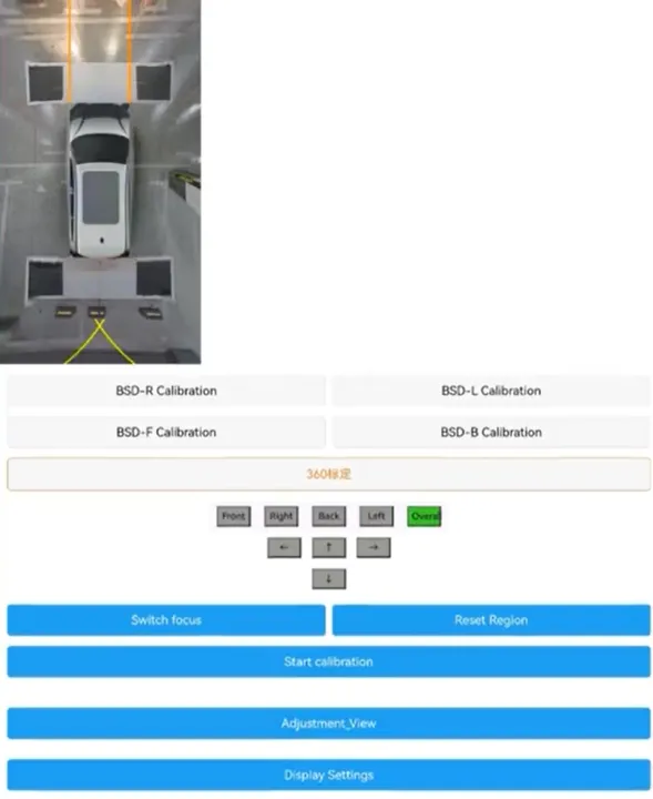
-
-
Custom ID
Section titled “Custom ID”